In this article, we will delve into the fascinating world of LNA SPICE simulation, exploring how to replicate and analyze the behavior of a Low Noise Amplifier using two powerful tools: LTspice and Matlab. By simulating an LNA’s performance, we can gain valuable insights into its characteristics, such as gain, noise figure, and bandwidth, and optimize its configuration for specific applications. Let’s now delve into the potential of LNA SPICE simulation techniques to deepen our understanding and improve our design skills.
A crucial component in the field of electronic circuits, the Low Noise Amplifier (LNA) plays a pivotal role in various applications where signal amplification is essential while maintaining the integrity of the original signal quality. An LNA, as the name suggests, is primarily designed to amplify weak electrical signals with minimal additional noise, ensuring a high Signal-to-Noise Ratio (SNR). This key attribute makes LNAs indispensable in numerous fields, including wireless communications, radio astronomy, broadcasting, medical imaging, and telecommunications, to name a few.
The fundamental purpose of an LNA is to boost the strength of incoming signals without introducing significant noise that could degrade the overall performance. In wireless communication systems, for instance, an LNA is positioned at the front end of a receiver to amplify faint radio frequency (RF) signals received from antennas or other receiving devices. By doing so, it enhances the receiver’s sensitivity, allowing it to detect and process weak signals effectively. Similarly, in radio astronomy, where astronomers seek to capture faint celestial emissions, LNAs are utilized to amplify these extraterrestrial signals while preserving their inherent low noise characteristics.
One of the distinguishing features of an LNA is its ability to maintain a low noise figure. The noise figure quantifies the extent to which an amplifier adds noise to the signal, and a lower noise figure corresponds to a better LNA performance. LNAs are meticulously designed to minimize thermal noise and other forms of electronic noise, ensuring that the amplified signal remains as clean as possible. This is especially critical in scenarios where weak signals must be distinguished from background noise or interference.
For those unfamiliar with LTspice software, you can find an LTspice tutorial here.
Ventspils University College
Faculty of Information
by
Marcis Bleider
LOW NOISE PREAMPLIFIER FOR SATELLITE BASE STATION
In this article low noise preamplifiers (LNA) for satellite ground station (GS) of Ventspils University College (VUC) are designed creating possibility to repair and replace these commercially expensive, extremely sensitive and easily damageable units.
One of main purposes of GS of VUC is for communication with soon to be launched satellite Venta-1. GS will provide uplink/downlink communication channels for satellite telecommands and telemetry in 2m and 70cm amateur frequency bands as well as main data downlink channel in s-band. GS also will (and are) communicate with other student satellites orbiting in low earth orbits (LEO), like Estonian Estcube-1 and Danish AAUSat cubesat series.
Because it is not always possible to receive and decode all data packets in particular satellite pass, skipped packets should be retransmitted in next pass – there are only few passes with acceptable elevation per day. Even though we are located very close to Estonia and Denmark and we are receiving same data as their ground station, our received data may contain packets that main station failed to receive, so data could be forwarded to main mission control center resulting in higher throughput. In any case, our station could be used as remote backup station, increasing redundancy of communication system.
Signals from satellites can be exquisitely weak, which means they need as much amplification as possible to be readable. The way to ensure that you have a useable received signal is to install a receive LNA at the antenna [1]. This is a high gain, low-noise amplifier with a frequency response tailored for one band only. Even though equipment of GS includes a few such preamplifiers, these units are very expensive, for example 2m/70cm band Kuhne Electronic LNAs costs 224 EUR per unit [6].
Because LNA is very sensitive device it is very prone to damage by lightening induced voltage spikes, static electricity and even by strong nearby radio transmission signals. Of course by correct system setup, like switchover relays, damage risk is greatly reduced, but LNA is still one of weakest link of the system in respect to failing. If device fails, it would be very non-economical to by new one each time, not to mention that it would not be possible to repair or replace it right away to reestablish operation of communication system as fast as possible.
In this work, theory of operation and typical design methods of LNAs are researched, and example design and testing procedure is described. For reference, two 70cm band LNAs are designed, built, tested and performance-price compared. In this particular paper, one 70cm LNA is designed and simulated with MATLAB using scattering parameter (s-parameter) and Smith chart method and LTSPICE software. It should be noted that preceding description is very superficial and only presentative.
The RF amplifier which is at the input stage of the receiver is usually designed to give the best gain parameter and the least noise. It is done so for the reason that the noise and distortion parameters would get depressed in the later stages of the receiver system [3]. Friis’s formula is used to calculate the total noise factor of a cascade of stages, each with its own noise factor and gain (assuming that the impedances are matched at each stage) [7]. The total noise factor can then be used to calculate the total noise figure is given in equation 1.
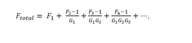
(1)
Where