Vittorio Carboni
Department of Electronics and Automatic, University of Ancona 1999/2000
SPICE simulations and analisys by Ing. Cristoforo Baldoni
1. Switching power supply: Choice of ferrite
2. Simplified calculation of the transformer
3. Transformer for Flyback converter: Calculation example
4. Transformer for Forward converter :Calculation example
5. Windings: Supports, wires and insulation
On what
How
With what
Skin and proximity effects
6. Let’ s complete the design of the flyback transformer
Primary
Secondary
Conclusions
7. Appendix
8. SPICE modeling of ETD49 N67 core from datasheet
9. Bibliography
1. Switching power supply: Choice of ferrite
The first step in the design of the transformer is the choice of the ferrite as physical form, type of material and dimensions. It’s a very important choice that characterizes the project as all subsequent calculations based on it. An error of assessment may lead, at the end of designing, to realize, for example, that the dimensions are not suitable: this means start again with considerable lost of time and resources.
The ferrites are characterized by very low losses at high frequencies, they are made with alloys of iron oxides and other metals such as zinc and manganese. The material is pulverized together with insulating oxides and then modeled using techniques typical of ceramics. This allows to make ferrites with a great variety of shapes and sizes and tolerances very restricted about magnetic and mechanically characteristics. They, also, can be machined with precision after the operation of the cooking.
The ferrites typically have a density of the saturation flux between 3 and 5 kGauss, also the presence of oxides increases its specific resistivity at very high levels thus allowing to reduce losses due to eddy currents. The available shapes include bars, toroids, EE EI and UI cores. The Curie temperature TC, namely the temperature at which the material loses its ferromagnetic properties, is between 100 and 300 ° C, depending on the type of material; the phenomenon is reversible, reducing the temperature to below the TC material regains its properties.
For low to medium power transformers E-Series is the best choice. As the acronym suggests, the magnetic core is composed of two elements in the shape of E. The two pieces forming the magnetic circuit, are slipped into the holder of the windings and locked in place with the clips and / or bonded with Araldite or other epoxy adhesives. The three contact surfaces of the half-cores are machined so as to reduce the roughness and therefore contain to negligible size the not intentional air gap . In some cases the air gap is desired, this can be obtained realizing the central column of the half-core shorter than outer ones.
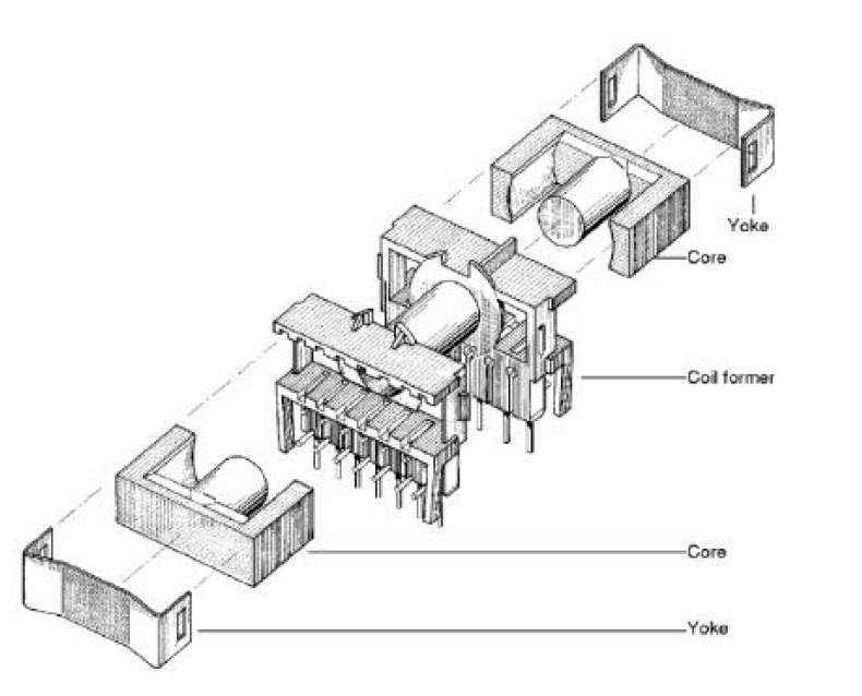
Figure 1 – Example of assembling of a kit composed of the support for the windings, a pair of ferrites of ETD type and a pair of fastening clips. (FERRITES and Accessories, Siemens Matsushita Components)
It’s possible choose from a catalog of half-cores with air gap calibrated. For the ferrite type ETD49, for example, we can have 4 values of the air gap: 0.20 +- 0.02 mm, 0.50 +- 0.05 mm, 1.00 +- 0.05, 2.00 +- 0.05 mm.
Coupling a half-core with air gap with another without, or also with air gap, also of different value, it is possible to obtain numerous combinations.
The ferrites of series E and ETD are widely used, so are easy to find. The catalog Siemens Matsushita indicates that the materials available for the E-series are different and coded with the initials N27, N67, N87, N49, N30, T37. The choice of material to use is correlated with the switching frequency: the type N27 is suitable for power applications in a frequency band of switching up to 100KHz, N67 is suitable for similar application, but the frequency range is between 100KHz and the 300KHz. Table 1 shows the possible applications for different materials. The E series has the classical central square column, other families in the same series are available for special applications such as the best known:
• ETD stands for Economic Transformer Design, with circular cross-section of the center column
• EFD stands for Economic Flat Design transformer for applications with space vertical content.

Table 1 – Some parameters for the type ferrites ETD (FERRITES and Accessories, Siemens Matsushita Components).

Table 2 – Maximum permissible temperature rise for different materials (FERRITES and Accessories, Siemens Matsushita Components).

Table 3 – Thermal resistance for different types and sizes of ferrite (FERRITES and Accessories, Siemens Matsushita Components).
The most important parameters for a correct choice of the ferrite are:
1. Maximum power (Ptrans)
2. Type of converter (Forward, Flyback, Push-Pull)
3. Switching frequency and maximum permissible temperature
4. maximum volume
To make the choice you might consider that the manufacturer, as a rule, always indicates the limit values, so if it is not pressing the issue of costs, it is a good idea to choose on the table, the type immediately above the one that delivers the requested power. This will avoid,later in the phase of winding, to discover that the number of turns calculated, with the wire section calculated does not enter for lack of space in the throat of the support of the windings. This precaution is especially recommended if the transformer should be wrapped in accordance with the safety standards (minimum distances between the different layers of the windings, using wire with double insulation etc..).
It follows an example of calculation of a switching transformer in [1]; the approach to this type of calculation is in many passages forcibly empirical, in many other simplified. On the other hand a completely theoretical discussion would result in a significant waste of resources without the benefits of improved performance.