Sub-Circuits for Proteus Simulation
This example demonstrates how to use Subcircuits. Let’s click on the ‘Subcircuit Mode’ button.

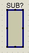
Click on the workarea and draw a rectangle like the one shown in the figure below
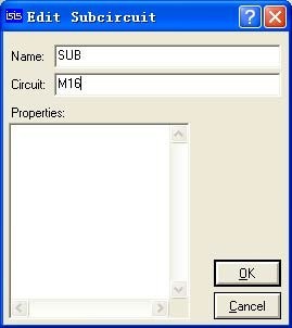
Right-click, select ‘Edit Properties,’ and an edit box will appear for modifying the properties:
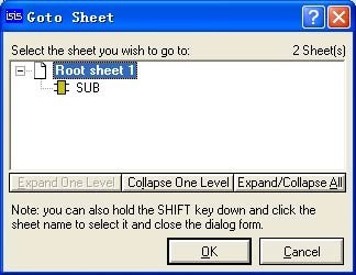
From the main toolbar, go to the Design menu and select the ‘Goto Sheet’ option
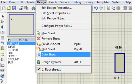
In the Hierarchy diagram, you will notice two images. We are currently working on the Root sheet 1, while SUB has just been generated, and its name corresponds to the name we edited in the Name property:
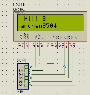
We want the SUB block to represent the ATmega16 microcontroller, which will interface with a 16×2 alphanumeric LCD. Now, let’s add the pins. Since the data transfer direction in this case is unidirectional, from the microcontroller M16 to the LCD, we will use only the OUTPUT pins. In the component list, select OUTPUT:
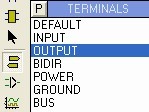
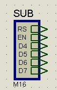
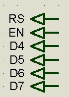
The pins can only be placed on the left and right sides of the SUB symbol. Add 6 pins and set their tag names using the following method: Right-click on the OUTPUT placed, left-click again, and enter the label name as a string
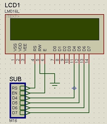
Now let’s connect the LCD, and this is the final result:
Once more, go to the Design menu, choose ‘Goto Sheet,’ and select ‘SUB,’ then click OK.

In the blank worksheet, add the ATMEGA 16 component. In the component list, select OUTPUT, add 6 pins, and give them the same label names as used for the SUB symbol:
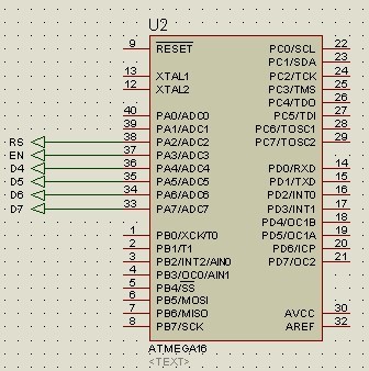
Connect the pins to the ATMEGA16. Load the hex file into the microcontroller and run the simulation. The final result is as follows: