Public info about the author: StevenSandler
- Profile
Steven M. Sandler is an internationally well known expert for power supply and RF design, simulation and measurements.

-

SPICE implementation for the 2-phase voltage-mode flyback converter. It uses 2 discontinous-mode flyback stages, operating 180 degrees apart for providing 200 Watt of active power.
- Free
- Advanced
- 31-50
- ICAP/4
- 8.1.6+
- Yes
-


-
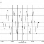
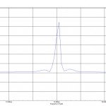
LC oscillator SPICE simulation with BJT 2N3904F. The oscillation frequency is 14.3 Mhz.
- Free
- Simple
- 11-20
- ICAP/4
- 8.1.6+
- Yes
-


-

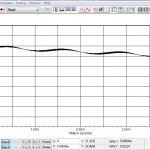
SPICE simulation of a full bridge inverter configuration. Output switches are used in place of MOSFETs or IGBT, in order to simplify and speed up the simulation.
- Free
- Intermediate
- 31-50
- ICAP/4
- 8.1.6+
- Yes
-

-

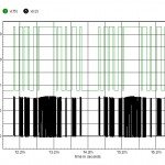
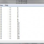
This SPICE simulation is performed with a state machine model, used to replace complex sets of circuitry. The block is described by an ASCII txt state file, where the first column defines the state, the second column defines the output for the state, the third column defines the expected input and the fourth column defines the state to transition to if the input is present during the positive edge of the clock signal. The state file of this circuit defines 128 states.
- Free
- Intermediate
- 11-20
- ICAP/4
- 8.1.6+
- Yes
-

-

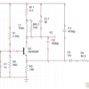
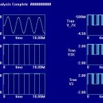
SPICE simulation of a static inverter with voltage regulation and current limit. The bit pattern is stored in the PWL state code file 64s.txt. A square wave at V(10) is filtered to create a ramp at the node V(ramp). B2 compares the combined outputs of the softstart, voltage error amp and current amplifier to the ramp, creating a 100kHz variable duty cycle that modulates the full bridge. D5, D6 and core X1 provide shoot thru protection for the Mosfets, while L3, C1 and C2 provide the output filtering to reconstruct the sine wave. X3 and the associated circuitry provides the current limit while L6 is a winding of the inverter transformer, used for voltage regulation.
- Free
- Advanced
- 31-50
- ICAP/4
- 8.3.11+
- Yes
-