
In relation to the PCB assignment, it’s worth mentioning that among the components, the animated red LED remains the sole element lacking an assigned footprint:
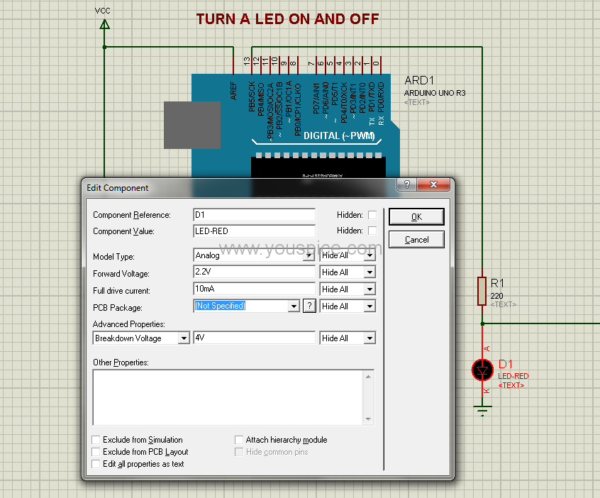
Fig. 6 PCB package not specified for the LED component
To address this, we need to allocate a footprint to it. Follow these steps: select the component, right-click, and opt for “Make Device:

Fig. 7 Make Device window
Proceed by clicking on “Next,” and then select “Add/Edit”:

Fig. 8 Click on “Add/Edit” button
The window for “Package Device” will be displayed:

Fig. 9 Package Device window
Click the “Add” button and input the keyword “led” within the “Pick Packages” window. From there, select the LED PACKAGE.

Fig. 10 Type “led” on Pick Packages window
Double-click on the first line located under the letter “A”:
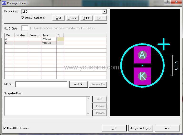
Fig. 11 Double click
Subsequently, click on the anode pin of the PCB:
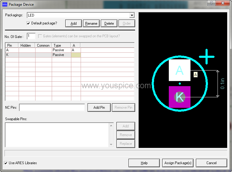
Fig. 12 Click on Anode pin
Follow the same procedure for the other pin:

Fig. 13 Click on Cathode pin
Now, proceed to click on the “Assign Packages” button

Fig. 14 Packagings window shows the PCB assigned
click on the “Next” button and opt for the PACKAGE from the Component Properties and Definitions options:
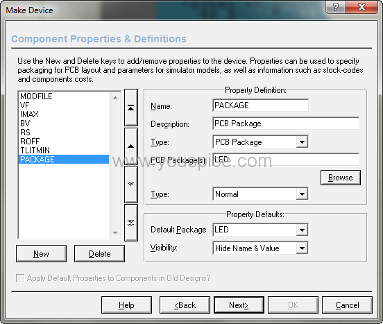
Fig. 15 Select PACKAGE
Keep the Datasheet Filename edit field empty:
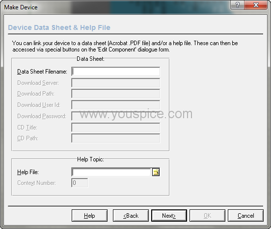
Fig. 16 leave blank the datasheet field
Select the USERDVC library, as an example:

Fig. 17 choose USERDVC library
Confirm the update request in the subsequent message box.

Fig. 18 Update message box